Infrared Solutions, Inc., a Fluke Company, has developed a new infrared technology called IR-Fusion™ that blends, pixel for pixel, visible and infrared images on a single display. This article describes the patent-pending, novel, low-cost approach to solving the parallax problem of combining images from separate visible and infrared optics.

Background
There are many reasons why visible images are generally sharper and clearer than infrared images. One is that visible sensor arrays can be made with smaller detector elements and with far greater numbers of elements. Another is that since visible images are not used to measure temperature, the images can be generated with only reflected radiation, which usually produces sharper images than emitted radiation.
Visible detector arrays have millions of elements while infrared detector arrays have far fewer. The Fluke FlexCam has a visible array with 1,360,000 detector elements and an infrared array with 1/18 as many (76,800 elements). As a result the visible image can have far more detail than the infrared image. In addition, the visible images can be displayed in the same colors, shades and intensities as that seen by the human eye so their structure and character are more easily interpreted than infrared images.
Although infrared and visible cameras can record radiation that is both emitted and reflected from a target, visible images are almost always produced by reflected visible light. In contrast, infrared images used to measure temperature must record emitted infrared radiation. Reflected visible radiation can produce sharp contrast with sharp edges and intensity differences; for example, a thin white line can lie next to a thin black line.
It is also possible to have sharp infrared reflection contrast by having a surface of low emissivity (high infrared reflectance) next to a surface of high emissivity (low infrared reflectance). But it is unusual to have surfaces with sharp temperature differences next to each other. Heat transfer between close objects can washout temperature differences by producing temperature gradients making it difficult to produce images of emitted radiation with sharp edges. This is another reason why infrared images that are used to measure temperatures are usually less sharp compared to visible images.
Industry needed a camera that could capture an image that showed the detail of a visible image and the temperature measurement of an infrared image. Most operators took duplicate images, one visible light and one infrared, but correlating the images was sometimes unreliable. The real need was for the two images to automatically overlay each other.
One proposal was to combine a visible and infrared camera side by side in one instrument so both images are taken simultaneously, but the spatial correlation suffered from parallax. It worked well at long distances where parallax is negligible. But for applications like predictive maintenance and building sciences where the camera is used at short to moderate distances, parallax is an issue.
Infrared Only Visible Only 50/50 Blend

Blended Visible and Infrared Images
The IR-Fusion technology combines a video-rate infrared camera with a video-rate visible-light camera into a single instrument so the scene can be viewed and recorded in both visible and infrared radiation. The visible image is automatically registered (corrected for parallax) and sized to match the infrared image, so the infrared scene and visible scene can overlay each other on the camera display. The operator can choose to view the visible image alone, infrared image alone, or a blended (fused) combination of the two. See example images in Figure 1.
Because the infrared and visible images are pixel for pixel matched by the camera, the operator can easily identify the location of infrared points-of-interest on the target by noting where the features are in the blended image. Once the infrared image is in focus, the camera operator may choose to view only the visible-light image and read the infrared temperatures on the visible image from data not displayed, but associated with the matching infrared image. An example of this can be seen in the visible-only panel of Figure 1, which shows the hottest spot at 121.7 °F.
With the blended image, the location of an infrared feature of interest can be precisely identified even if the infrared contrast is low and there is very little structure in the infrared image. In Figure 2, the exact location of a poorly insulated spot on a flat wall or ceiling is aided by seeing a small visible blemish or mark in the blended visible/infrared image.
Display Modes
Fluke Ti4X and 5X Infrared Cameras with IR-Fusion™ can operate in five display modes; 1) Picture-in-Picture, 2) Full-Screen and 3) Color-Alarms, 4) Alpha Blending, and 5) Full visible light. In any of the first four modes, temperatures are recorded and can be displayed in the infrared portion of the image.
Blended

Visible Only Infrared Only Moderate Blend

75 % IR Blend 50 % IR Blend 25 % IR Blend

Visible Only Infrared Only 50/50 Blend

- Picture-in-Picture Mode (Figure 3); In the picture-in-picture mode, the center quarter of the display is infrared-only, visible-only or a blend of the two. The remaining three quarters of the screen is visible only. In this mode, the infrared image is always displayed in a fixed position in the middle of the display.
Figure 4 shows a blended image with different percent infrared blending. - Full-Screen Mode; In the full-screen mode the center quarter of the picture-in-picture mode fills the screen. As in the picture-in-picture mode, the full display can be visible-only, infrared-only or a blend of the two. Figure 5 shows a full screen image of the same infrared scene shown in Figure 4.
- Color-Alarm Mode; The color-alarm mode is used to highlight areas of interest that meet particular temperature criteria set by the camera operator. Three settings are available; a) hot threshold, b) cold threshold and c) absolute range.
- In the hot threshold mode, any pixel in the image with a temperature above a temperature setting will appear in infrared colors.
- In the cold threshold mode, any pixel in the image with a temperature below a temperature setting will appear in infrared colors.

Figure 6. Color-alarm example with hot threshold set at 300 °F - In the absolute range mode (isotherm), the camera operator specifies both an upper and lower temperature of a range. Any pixel with a temperature in this range will appear in infrared colors. In all color-alarm modes, the colors are set by the infrared palette selection and the intensity by the degree of infrared blending. The mode display can be set as either picture-in-picture or full-screen.
How blending is accomplished
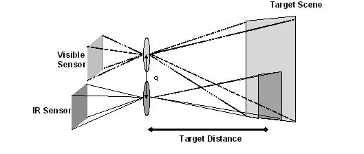
The IR-Fusion™ technology places the engine of a real-time visible camera in the housing of a real-time infrared camera. The placement is such that the visible optical axis is as close to the infrared optical axis as practical and is roughly parallel to the infrared axis in the vertical plain. In order to correct for parallax for a range of target distances, the field of view (FOV) of one of the cameras must be larger than the other. The visible FOV was chosen larger because visible optics at the present time is less expensive than infrared optics and visible cameras have far finer resolution. Therefore, losing some of the visible image through the parallax correction process has the least impact on the camera and blended images.
Diagram 1 shows the optical path and sensor configuration of the combined infrared and visible camera. There are two distinct optical paths and two separate sensors; one for visible and one for infrared. Because the optical paths for the sensors are different, each sensor will "see" the target scene from slightly different views causing parallax error. This parallax error is corrected in the combined image electronically with software adjustments.

The visible optics is such that it remains in focus at all usable distances. The infrared lens has a low f-number and as a result a shallow depth of field which provides an excellent means of determining distance to the target. Only the infrared lens needs focus adjustment for targets at different distances.
Parallax correction
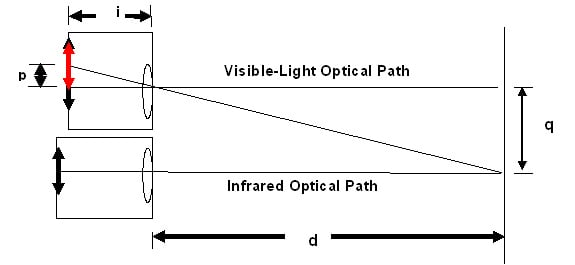
The parallax correction is based on the infrared focus distance. Diagram 2 shows geometrically, the derivation of the parallax equation.
From the standard lens equation
Where; d = distance to object
i = distance to image
f = effective focal length of lens
And from Diagram 2:
Where; q = separation distance between visible and infrared optical axis p = image offset at the visible focal plane
For a given camera the separation distance q and the lens focal length f are fixed. Therefore from the above equation the visible image offset is a function of the target distance only. q d Infrared Optical Path p i d Visible-Light Optical Path

When an image is captured, the full visible image and the full infrared image with all the ancillary data are saved in an image file on the camera memory card. That part of the visible image not displayed which lies outside the display dimensions when the image was taken is saved as part of the visible image. Later, if post processing adjustment in the registration between the infrared and visible image is needed on a PC, the full visible image is available to make such adjustments.
Conclusion
A novel approach to solving the parallax issue for a camera with both visible and infrared optics has resulted in a commercial camera that significantly improves the performance and usefulness for predictive maintenance and building sciences applications. Specifically it provides greatly improved spatial detail to infrared images and aids in identifying the exact location of infrared points-of-interest.
Acknowledgment
The author, Roger Schmidt, wishes to acknowledge the exceptional work by the Infrared Solutions, Inc. Engineering Team in inventing and developing this unique camera. The team was led by Kirk Johnson and Tom McManus and supported by Peter Bergstrom, Brian Bernald, Pierre Chaput, Lee Kantor, Mike Loukusa, Corey Packard, Tim Preble, Eugene Skobov, Justin Sheard, Ed Thiede and Mike Thorson. The author also wishes to acknowledge the work of Tony Tallman for the PC software that made it easy to provide these revealing images in the paper.
