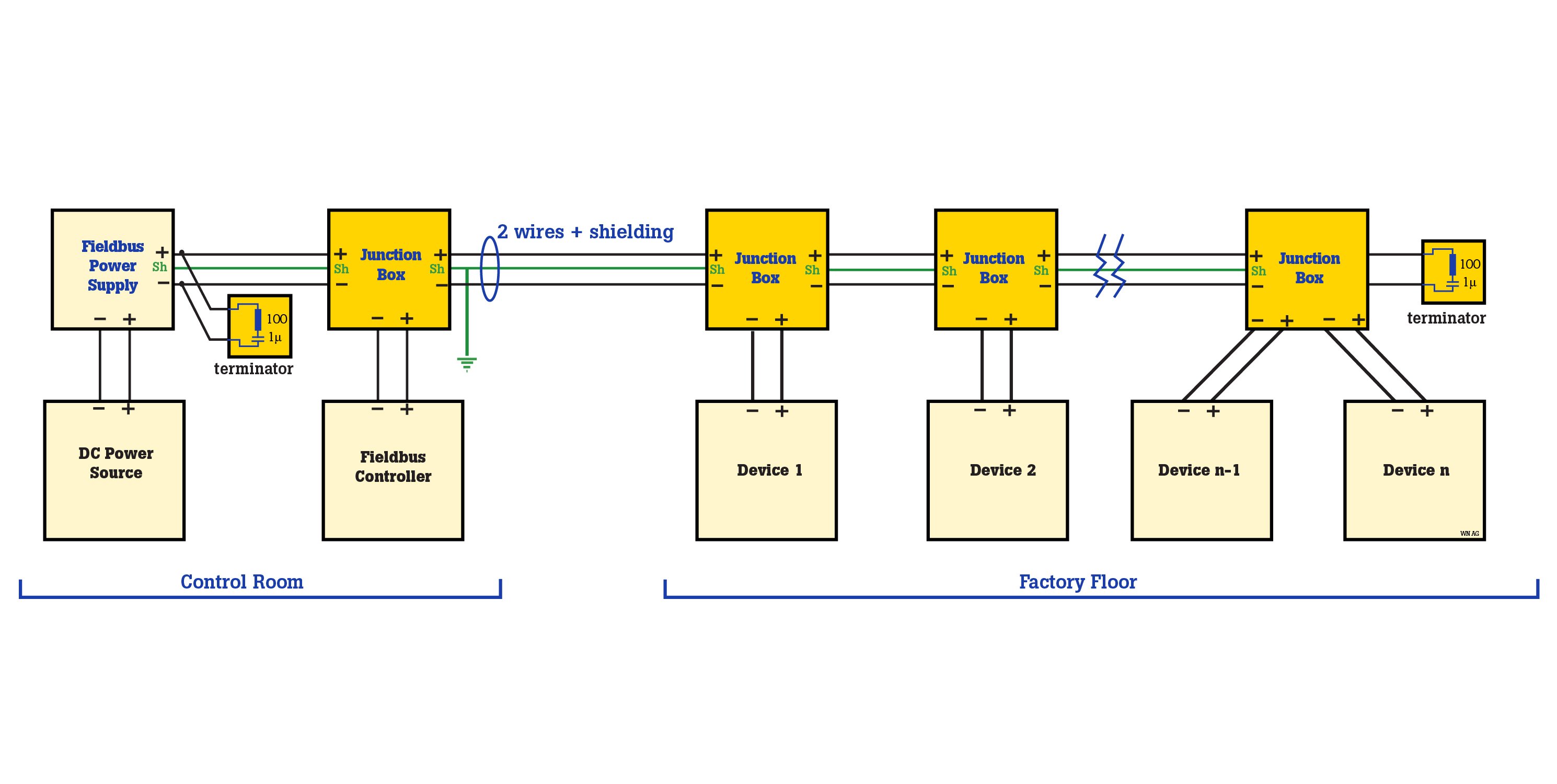
In the last decade or so the trend in factory automation has been to replace the traditional control scheme, where each device has its own control wiring, with bus systems that link multiple devices through the same cable. One of the most popular and widely used bus systems is Foundation Fieldbus, which includes two different protocols–H1 and HSE (High-speed Ethernet) protocol. Each of those protocols meets different needs within the factory automation environment and uses different physical media and communication speeds. This discussion will focus on the H1 protocol.

The H1 protocol operates at 31.25 kb/s and generally connects to field devices such as sensors, actuators, valves, control lights, and I/O devices. It allows two-way communication between devices and a controller and provides both communications and power over a two-wire system.
Industrial fieldbus networks operate under very different conditions than those for office and other commercial communications networks. In the industrial environment, disruptive environmental conditions and electrical disturbances can play havoc with sensitive electronic devices such as PLCs, network controllers and other instruments that support process control.
To quickly find these problems common practice is to monitor and troubleshoot industrial digital communications systems with a portable oscilloscope, like a Fluke 120B Series ScopeMeter® Test Tool.
Troubleshooting an industrial fieldbus system
Evaluate the symptoms:
- The first step when troubleshooting an H1 Fieldbus system, is to document any recent changes to the system. Have any devices or parts of the network recently been disconnected? Was anything added or modified just before the trouble began?
- Determine what's working and what's not. Make notes about observed operation versus what was expected.
- Where disturbances occur see if they can be traced back to specific events such as a motor starting, a valve opening, or a light being turned on.
What to measure:
- Make measurements to "look into" the network in order to see and understand what's going on. Carefully document each measurement, including what was measured and under what conditions. Some of the most useful measurements for this include:
- Capacitances and resistances in and between conductors.
- Shield and conductor contacts.
- DC voltages.
- AC signal levels.
- Noise and signal quality.
Where to measure:
- In some cases the symptoms quickly narrow down the location of the problem which means you can narrow your investigation:
- If only one device has a problem, take measurements near that device.
- If multiple devices have problems, try to determine if there is a pattern; if there is, determine whether the cause is evident.
- In cases where the location of the problem is not as obvious, try to determine which segments, if any, of the network have problems and which are problem free:
- Measure at both ends of the trunk cabling and compare the results.
- Measure at one or more locations along the trunk and compare the results.
- If modifications have been made or devices added recently, take measurements at these locations.
Once the tests described here are completed, analyzing the collected data as a whole should help you draw conclusions about what is happening on the network and locate the weak spots that need attention.