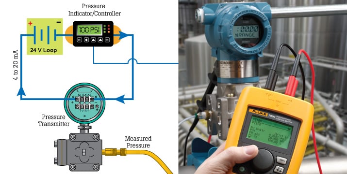
The mA simulate function of a loop calibrator is very useful for testing and troubleshooting 4 to 20 mA process control loops. In mA simulate, a loop calibrator essentially replicates the function of a process instrument when connected in place of the transmitter. The mA simulate function is often referred to as transmitter simulate on the loop troubleshooting tool. In mA simulate mode, the loop calibrator is technically a mA sink. This means it regulates a programmed mA signal value and draws power from the loop 24V power supply.

Find the right loop calibrator
When to use mA simulate
If a loop is operating erratically and a pressure transmitter for example is suspected of being defective disconnect wires from the transmitter being careful to note which wire was removed from the positive and negative terminals. Connect the test leads of the loop calibrator to the wires removed from the transmitter. Be careful to connect with the correct polarity, black test lead (-) to wire that was connected to the negative terminal of the transmitter, red to the positive wire. Select mA simulate mode and set the loop calibrator to a mA signal value.
With 4 mA simulated by the loop calibrator the HMI or controller that is connected in the loop should indicate the 0% (lower range pressure setting) value of the transmitter. With the mA simulate signal set to 20 mA the indicator or HMI should indicate the 100% or upper range pressure value of the transmitter.
How to interpret mA simulate results
Deviations between the expected read out value and the actual value would indicate that the A/D converter of the controller input card needs adjustment. If there is no value indicated and/or the loop calibrator indicates an open circuit check to see if the input card is defective or if the input fuse in the card is open. If there is no voltage the 24v loop power supply may be defective. Check for an open fuse on the input card with a digital multimeter set in continuity or resistance measurement. The measured value should be somewhere between 100 and 250 ohms. To check if the 24V power supply is operating correctly measure the voltage at the transmitter wires when disconnected. The full 24V should be measured. If not, the power supply is either defective, overloaded or there is an open connection or termination.
Using mA simulate to test a process control loop is very powerful in that it tests the signal wires, 24V loop power supply and the input of the control system. If a loop that was operating erratically operates correctly doing this test the problem with the loop is likely the transmitter or its' input sensor.