To measure ac or dc voltage:
- Turn the meter's dial to the proper voltage function ().
- Connect the black test lead to the COM terminal and the red test probe to the V terminal, indicated by on the Fluke 381.
- Measure the voltage by touching the probes to the desired test points of the circuit.
- View thereading in the display.
To measure resistance or continuity:
- Turn the dial to .
- Remove power from the circuit being tested.
- Connect the black test probe to the COM terminal and
- The red test probe to terminal.
- Measure the resistance by touching the probes to the desired test points of the circuit.
- View the reading on the display.
If the resistance is < 30 Ω, continuity is indicated by a beeper continuously sounding. If the display reads OL, the circuit is open or the resistance being measured is greater than the meter's resistance range.
To measure frequency (on the Fluke 381):
- Turn the dial to .
- Center the jaw or flexible probe around the measurement source.
- Push the yellow shift button ( on the Fluke 381) to shift to Hz.
- View the measurement in the display.
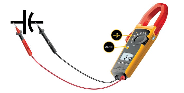
To measure capacitance (on Fluke 370 series clamp meters)
- Turn the dial to .
- Remove power from the circuit being tested.
- Connect the black test probe to the COM terminal and the red test probe to the terminal.
- Measure the resistance by touching the probes to the desired test points of the circuit.
- View the reading on the display.
