The number of solar installations around the country is growing faster each year, creating an ever-increasing demand for technicians who know how to troubleshoot photovoltaic (PV) systems efficiently and effectively.

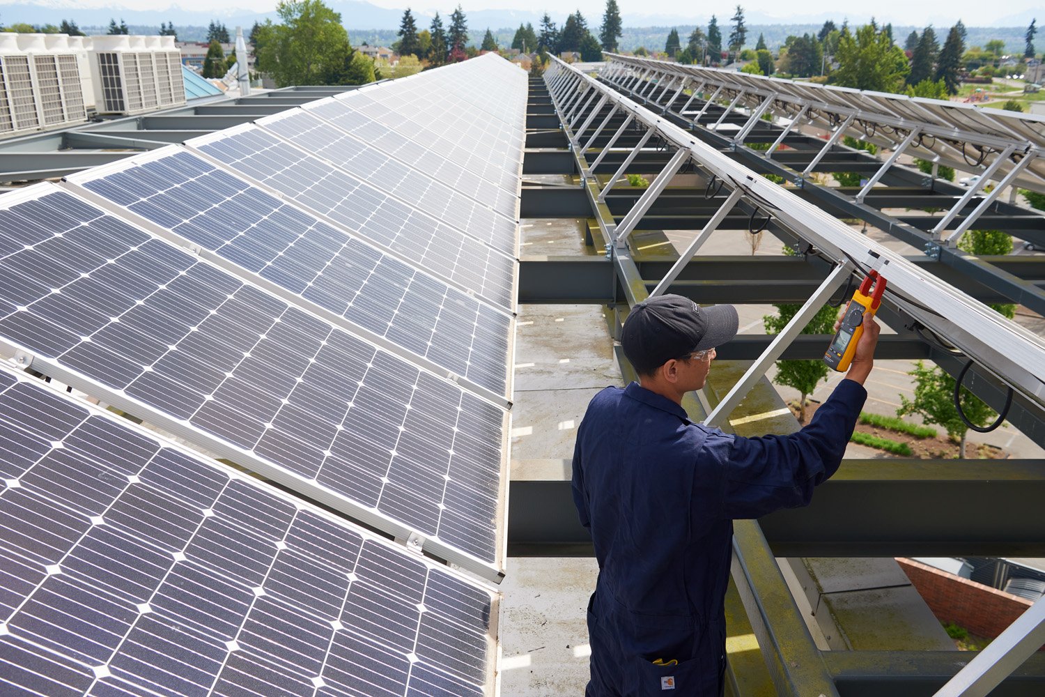
Troubleshooting a PV solar photovoltaic system will typically focus on four parts of the system: the PV panels, load, inverter, and combiner boxes.
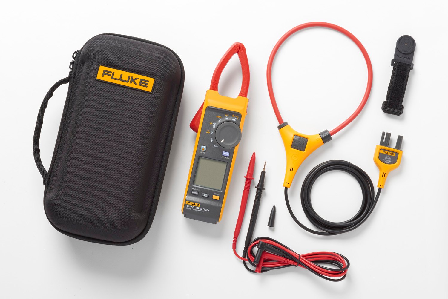
The all-around best tool to use for working in most areas of a solar installation is the Fluke 393 FC CAT III 1500 V Solar Clamp Meter . This is the world's only CAT III 1500V rated, IP 54 ac/dc clamp meter with features — such as dc power, audio polarity, and visual continuity — that are tailor-made for test and measurement in solar PV applications.

1. Troubleshooting Solar Photovoltaic System PPV panels
First check the output of the entire system at the metering system or inverter. Before you begin troubleshooting, check and record the inverter's input voltage and current level from the array. You will likely encounter one of two scenarios:
- The entire PV system, or a portion of it, is down or not producing power; this may be related to a problem with the inverter.
- Or the PV system output is less than expected; this may be related to a problem with one of the arrays or modules.
Trace out the individual branch wiring backward from the concentrator. Check the entire system visually for any obvious damage or accidental disconnections. Once you find the failed module or array, check all wires, switches, fuses, and circuit breakers. Replace blown fuses; reset the breakers and switches. Check for broken wires and loose or dirty connections; replace and clean as needed. Be on the lookout for loose connections between the modules. They may have worked loose and caused lack of contact.
The combiner box can be a great place to troubleshoot the system because the individual wires from the modules are brought back to it. Each module may have a fuse that you should check with your Fluke 393 FC.
Wiring problems and loose connections may also cause a module to produce too low a voltage. Check all wiring connections. If a module output is low, it may mean that an individual section of cells is bad. These can be traced out using the 393 FC at the junction boxes until the culprit is found.
The Fluke 393 FC provides an audio polarity warning when you’re testing Voc. If you find that polarity is reversed, it may mean that other circuits in the combiner box are unintentionally connected in series, resulting in voltages over the maximum inverter input voltage.
Any dirt or shade on the modules themselves can cause reduced output. Although the modules are usually designed to be maintenance free for years, they may need to be cleaned. Pollen and dust can be a significant problem in some areas of the country.
2. Troubleshooting Solar Photovoltaic System LPV loads
The PV system is used to operate building electrical loads; any problems with the loads will affect the system as well. The first step is to check the load switches, fuses and breakers with the Fluke 393 FC to see if the proper voltage is present at the load's connection. Next, use the 393 FC to check the fuses and circuit breakers. If you find blown fuses or tripped breakers, locate the cause and fix or replace the faulty component. If the load is a motor, an internal thermal breaker might be tripped or there might be an open winding in the motor. For testing purposes, plug in another load and see if it operates properly.
As with any electrical system, check for broken wires and any loose connections. Clean all dirty connections and replace all bad wiring. With the power off, check for and repair any ground faults. If any fuses or breakers blow or trip again, there’s a short that you need to locate and repair.
If the load still does not operate properly, use the Fluke 393 FC to check the system's voltage at the load's connection. The wire size may be too small and need to be increased. It may also be possible that that the wires running to the loads are too long. This will show up as a low voltage at the load. In this case you can reduce the load on the circuit or run a larger wire.
3. Troubleshooting Solar Photovoltaic System IPV inverters
You likely work with variable speed drives every day, so are used to checking ac and dc power. The inverter in a PV system can also fail and cause problems. The inverter converts dc from the PV system into ac power for building use.
If the inverter isn’t producing the correct output, first use check and record the inverter's operating dc input voltage and current level. On the ac side, use the Fluke 393 FC to check the inverter's output voltage and current levels. Many of these systems have a display that indicates current inverter and system performance. Because the 393 FC produces a true-rms reading, you can use the voltage and current to measure and record the kilowatt (kW) output. If possible, use the inverter display to show the current total kilowatt hours (kWh). You can then write down this value and compare it to the one recorded during the last inspection. On the dc side, you can use the 393 FC to check the dc power and save the reading to the Fluke Connect™ app on your phone.
If the inverter does not produce the right amount of power, there may be several problems — all of which you can easily check with the Fluke 393 FC:
- Blown fuse
- Tripped breaker
- Broken wires
Use the 393 FC to measure the output ac side of the inverter; the load on the inverter might have a current demand that’s too high. With the dual display showing ac voltage and frequency, you can determine whether the inverter ac output is operating correctly.
The inverter may be tied into the local utility. The ac current output from the inverter fluctuates with the level of solar input on the array. The inverter maintains the correct output voltage and phase to the utility. Any voltage problems from the utility may cause the inverter to shut down. In that event, contact the utility for repairs.

4. Troubleshooting Combiner Boxes
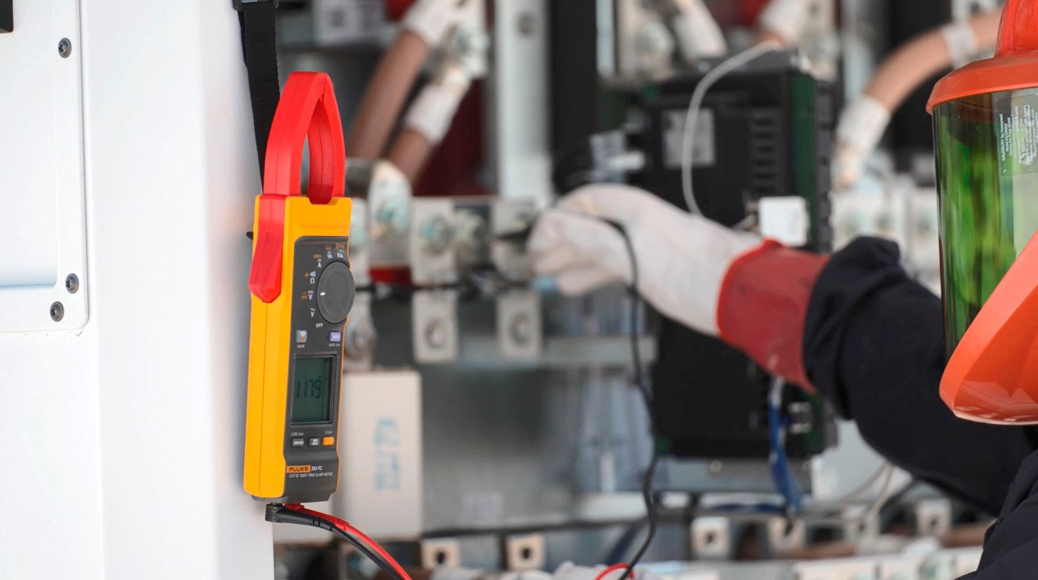
When you’re troubleshooting combiner boxes, amperage measurements and calculations are crucial to establishing whether the PV arrays are operating correctly. Measuring current on individual arrays or combining current measurements will help you determine if a cell has malfunctioned.
The thinner jaw design of the Fluke 393 FC clamp meter lets you get several conductors in the jaw for combined current measurements, even in tight or crowded spaces like inverter or combiner boxes.