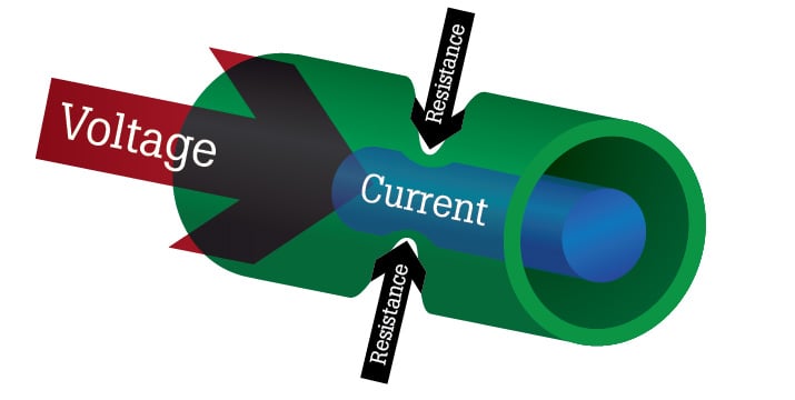
Resistance is a measure of the opposition to the flow of current in an electrical circuit. It is influenced by the material's properties, length, cross-sectional area, and temperature.

What is Electrical Resistance?
Resistance is measured in ohms, symbolized by the Greek letter omega (Ω). Ohms are named after Georg Simon Ohm (1784-1854), a German physicist who studied the relationship between voltage, current and resistance. He is credited for formulating Ohm's Law.
Types of Materials and Their Resistance
All materials resist current flow to some degree. However, when it comes to resistance, most materials fall into one of two broad categories:
- Conductors: Materials that offer very little resistance allow electrons to move easily. Examples: silver, copper, gold, and aluminum.
- Insulators: Materials that have high resistance restrict the flow of electrons. Examples: Rubber, paper, glass, wood, and plastic.

Measuring Resistance
Before measuring resistance, it’s important to know how your measurement tool displays results. Resistance measurement results look very different depending on if you’re measuring in ohms (Ω), kiloohms (kΩ), or another unit. Also, to ensure you get an accurate reading, make sure the component you’re testing is powered down or disconnected from the circuit.
Tools and Instruments Used to Measure Resistance
Electrical resistance can be measured by using either a multimeter or an ohmmeter. A multimeter is a multifunctional tool that can measure voltage, current, resistance, and other types of electrical measurements, depending on the style of the multimeter. An ohmmeter only measures resistance.
Units of Measurement for Electrical Resistance
Electrical resistance is measured in ohms, represented by the symbol Ω.
One Ω represents the electrical resistance between two points when a voltage of one volt applied across the points results in a current of one ampere, or amp.
Standard Procedures for Measuring Resistance
- When measuring resistance, always ensure the power to the system is off and that any capacitors are discharged.
- Turn the multimeter to the resistance setting. It’s often marked with the symbol Ω.
- Insert the black lead into the COM jack and the red lead into the VΩ jack.
- Connect the test leads across the component being tested.
- Read the measurement displayed on the multimeter, noting the annunciator (such as K or M) after the measurement.
Factors Affecting Resistance
Resistance measurements are normally taken to indicate the condition of a component or a circuit.
High Resistance Cause and Effect
The higher the resistance, the lower the current flow. If the resistance is abnormally high, one possible cause (among many) is damaged conductors due to burning or corrosion. All conductors give off some degree of heat, so overheating is an issue often associated with resistance issues.
Low Resistance Cause and Effect
The lower the resistance, the higher the current flow. If the resistance is abnormally low, it could be due to insulators that were damaged by moisture or overheating.
Fixed-Resistance Components
Many components, such as heating elements and resistors, have a fixed-resistance value. These values are often printed on the components' nameplates or in manuals.
When a tolerance is indicated, the measured resistance value should be within the specified resistance range. Any significant change in a fixed-resistance value usually indicates a problem.
Practical Applications of Resistance
"Resistance" may sound negative, but when it comes to electrical systems, it can be used beneficially.
For example, thanks to high resistance, current struggles to flow through the small coils of a toaster, generating enough heat to toast bread. Old-style incandescent light bulbs also force current to flow through thin, high-resistant filaments, which then heat up enough to produce light.
Measuring Resistance in Circuits
Resistance cannot be measured in an operating circuit. Accordingly, troubleshooting technicians often determine resistance by taking voltage and current measurements and applying Ohm's Law:
E = I x R
This means that the voltage (E) across a circuit is equal to the current (I) flowing through it times the resistance (R). That is, volts = amps x ohms. If resistance is unknown, the formula can be converted to R = E/I (ohms = volts / amps).
Examples of Circuit Resistance
Normal Circuit Resistance
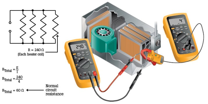
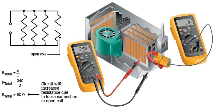
In an electric heater circuit, as portrayed in the two illustrations below, resistance is determined by measuring circuit voltage and current, then applying Ohm's Law.


In the first example, total normal circuit resistance, a known reference value, is 60 Ω (240 ÷ 4 = 60 Ω). The 60 Ω resistance can help determine the condition of a circuit.
Increased Circuit Resistance
In the second example, if circuit current is 3 amps instead of 4, circuit resistance has increased from 60 Ω to 80 Ω (240 ÷ 3 = 80 Ω). The 20 Ω gain in total resistance could be caused by a loose or dirty connection or an open-coil section. Open-coil sections increase the total circuit resistance, which decreases current.
Troubleshooting with Resistance Measurements
Knowing the electrical resistance in a circuit or component can be useful when troubleshooting electrical problems. Measuring resistance is a straightforward way to identify whether components are operating properly.
By measuring resistance at different points in a circuit, you can pinpoint where the failure is and more quickly restore the circuit to its proper operation. Failed components, weak connections, or damaged insulation can all be diagnosed by measuring resistance.
Identifying Common Issues Using Resistance Measurements
Some of the common issues that electrical resistance measurements can help identify include:
- Open or short circuits: High or infinite resistance indicates an open circuit, while very low or zero resistance indicates a short circuit.
- Failed components: Components such as resistors have known resistance, and testing their resistance can indicate if they are faulty.
- Overheating components: Components that overheat often have higher resistance than normal, indicating potential issues.
- Voltage drop issues: Measuring the resistance of conductors can help locate sections of the wiring that may need to be replaced or connections that should be tightened.
Techniques for Diagnosing Problems in Electrical Circuits
To use electrical resistance measurements to diagnose problems in electrical circuits, follow these steps:
- Turn off the power.
- Complete a visual inspection, checking for signs of physical damage, loose connections, or corrosion.
- Isolate the components in the circuit to be tested.
- Select the appropriate resistance range for each component before testing.
- Test each component for resistance, noting the values and comparing them to the expected values.
- Analyze the results by using the measured resistances to diagnose the issue, whether it’s an open circuit, a short circuit, or a high-resistance component that needs to be replaced.
About Electrical Resistance
Electrical resistance is an important property of electricity that controls the flow of current in electrical systems. It can also be a key indicator of installation errors, poor connections, and failed components. While resistance can be determined using Ohm’s Law, it can also be measured with specialized tools like a multimeter or ohmmeter. Understanding how to properly measure electrical resistance can help you diagnose problems with electrical systems and ensure their reliability and safety.