Infrared cameras allow you to conduct inspections from a safe distance. That means you may not have to shut down the operation or suit up in full personal protective equipment. They save production time as well as help prevent exposure to hazardous environments. However, for some applications, you need to capture images of objects that would be very difficult to get close enough to without entering a danger zone, climbing a ladder or maybe even using a lift or a helicopter. You are going to need a lens add-on for your camera. High-quality telephoto and macros lenses are often called “smart lenses”, as they require no calibration for use with a specific camera. They can also be used interchangeably with other compatible infrared cameras.
4x and 2x telephoto infrared lenses magnify your view so you can see a lot more detail from the ground or from a safe distance. Alternatively, 25 micron macro lenses provide a level of thermal detail that help you identify problems that you wouldn’t be able to catch with a standard lens. This level of detail is critical for ensuring the design integrity and production quality of constantly shrinking PCBs and microelectronic components.
High-quality telephoto lenses go far beyond simply bringing the image closer. They can help you capture enhanced details while increasing your spatial resolution to help you see and possibly even measure an anomaly that you might not have been able to see with the standard lens. This can help you assess the possible issue while still on site These telephoto lenses fit a wide range of applications including power generation, power transmission, and power distribution; chemical and oil and gas manufacturing; metals refinement; building inspection or any large industrial or commercial operation.
When to use a wide angle lens
Wide angle lenses are best for viewing large targets from a relatively close distance. If you need to view a large area or are working in a tight space, which is particularly useful for electrical, maintenance, and process technicians. And building inspectors can use these lenses for inspecting roofs and industrial buildings, as they can see a larger area at once.
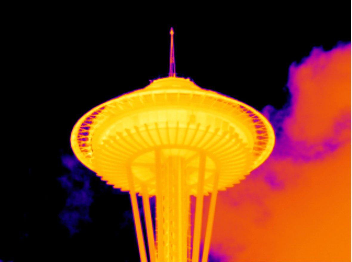
This image was captured with a TiX560 infrared camera and a Fluke 2x telephoto infrared lens.
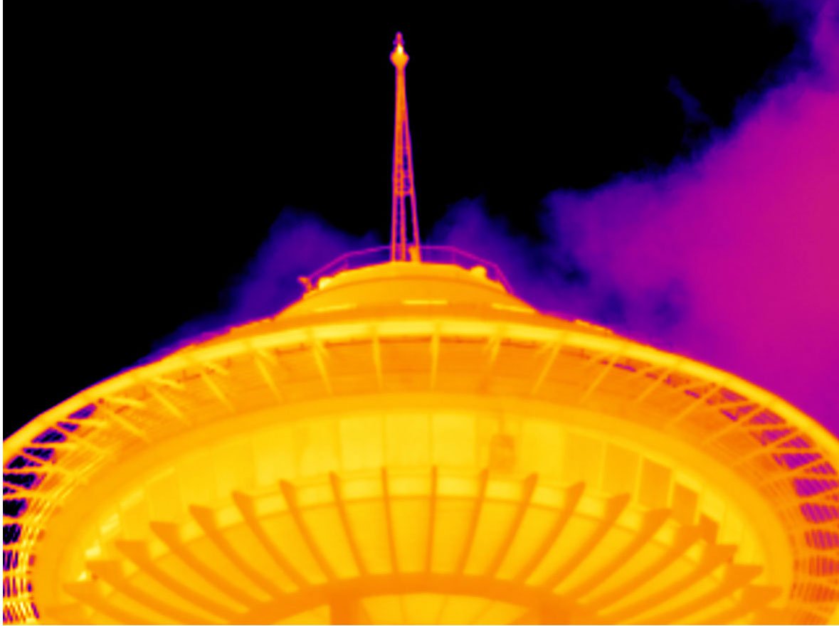
This image was captured from the same location with a TiX560 infrared camera and a Fluke 4x telephoto infrared lens.
When to use a 2x telephoto lens
2x telephoto lenses are a good choice for small to medium sized targets when you cannot get quite close enough to see the needed detail with a standard lens. For example, if your infrared camera with a standard lens has a D:S ratio of 764:1, then you could stand 764 cm (7.6 meters, 25.1 feet) from an object and see a spot size of 1 cm (.4 inches). With the same camera and a 2x telephoto lens your D:S will approximately double, giving you ~1530:1 (15.3 m (43.6 ft) from a 1 cm (.4 in) spot). This would give you the ability to see the same spot size from nearly twice the distance or approximately 0.5 cm2 (.2 in2) area from the same distance.
The 2x lens provides quite a bit more detail than the standard lens. That means it can reduce your need to enter the hazard zone in your plant or to climb a tall ladder to capture critical troubleshooting or maintenance data. This makes it very useful for inspecting electrical, electromechanical, and process equipment. It is also a good choice for scanning overhead vents, duct work, or wiring or possibly for scanning below grade to see details in a vault or a small sump.
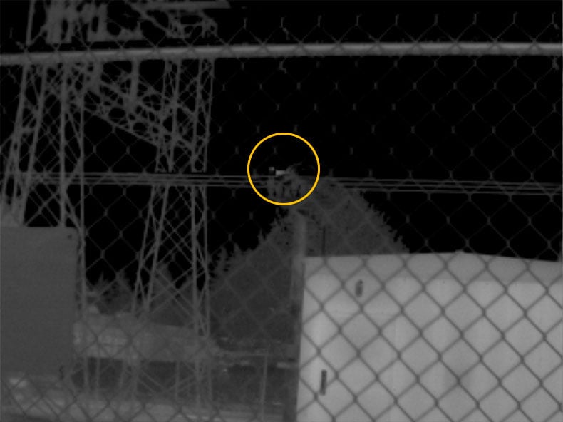
An exterior scan of exterior equipment at a substation with a TiX560 infrared camera and a standard lens captured an anomaly on one of the phase switches.
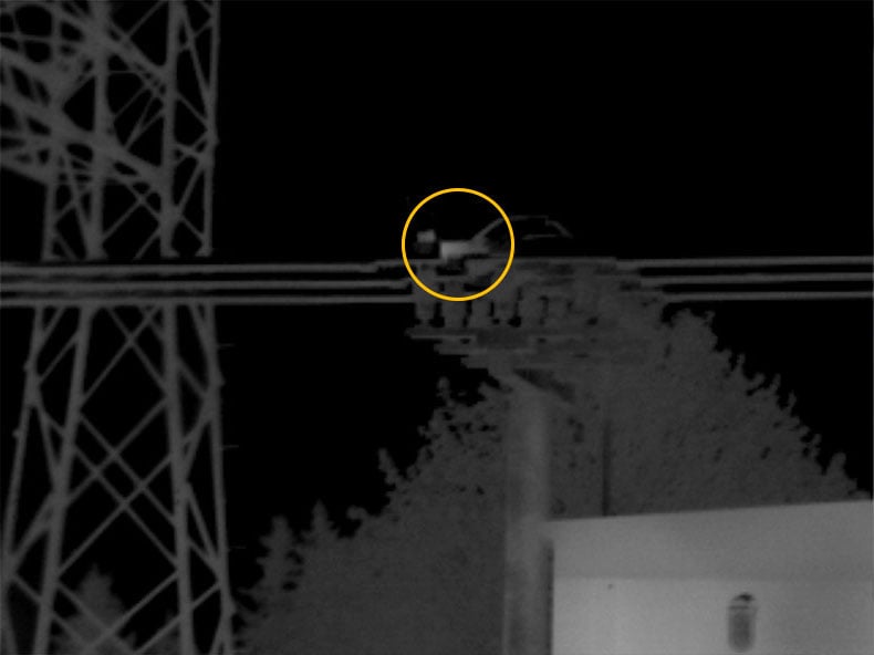
Scanning the same area with a Fluke 2x telephoto lens shows a definite hot spot on the switch.
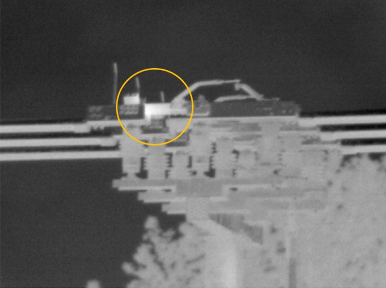
This third image of the substation transmission line, captured with a Fluke 4x telephoto lens clearly shows a hot spot or high resistance on a knife switch.
When to use a 4x telephoto lens
4x telephoto lenses are excellent for capturing thermal profiles of small targets from a much greater distance. For example, if the D:S of your infrared camera is 764:1 with the standard lens, it would be approximately 4x that—~3056:1—with a 4x telephoto lens (30.6 m (100.3 ft) from a 1 cm (.4 in) spot). So, if you stand 7.6 meters from the object you would detect a spot size approximately 0.25 cm2 (.1 in2). A 4x telephoto lens is an excellent choice for many applications including:
- Overhead transmission lines
- Power substations
- Tall stacks in petrochemical plants
- Metals refinement
- Other hard to reach, energized or unsafe areas
With a 4x telephoto lens, you can see critical detail from a distance that would not be easily viewable any other way, so you can identify potential issues on a transmission line splice or failing refractory that could create product quality issues, an unsafe working environment, and/or lost revenue.
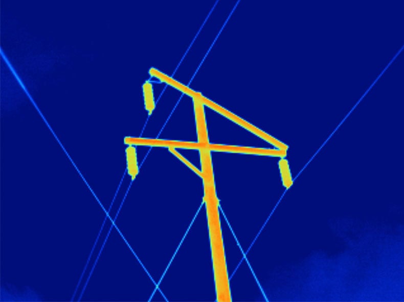
High voltage power pole, captured with a TiX560 camera and standard lens.
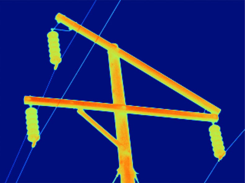
The same power pole captured from the same distance as the previous image, but with a Fluke 2x telephoto lens.
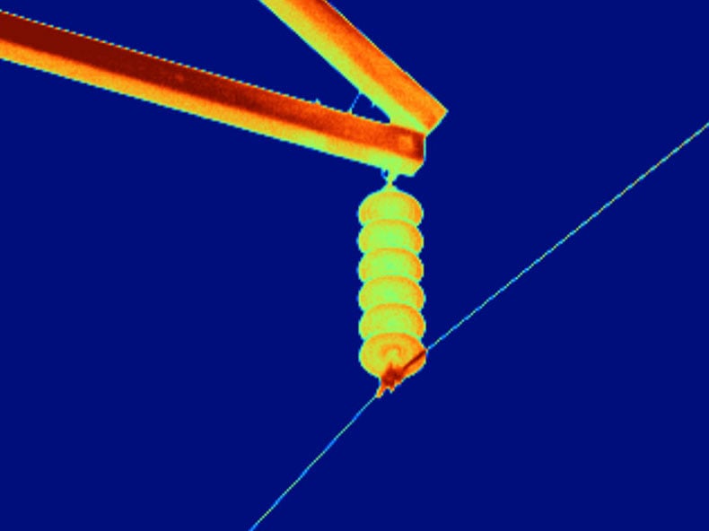
The right-hand connection point captured from the same distance as the first image but with a Fluke 4x telephoto lens. The 4x telephoto lens gives you the level of detail needed to verify whether you have a possible issue or if maybe it's just a reflection, as in this case.
Putting macro lenses to work
Whether you’re designing a new device, running quality control tests on components or fully assembled boards, or troubleshooting finished devices, the ability to see minor differences in thermal profiles of microelectronic components can help you diagnose trouble spots or pass boards or components faster.
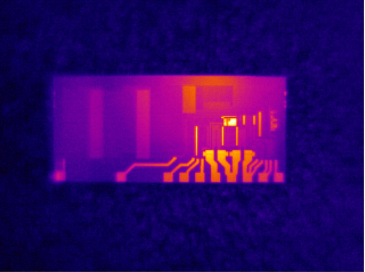
Precise resistance chip taken with standard lens and Fluke TiX560.
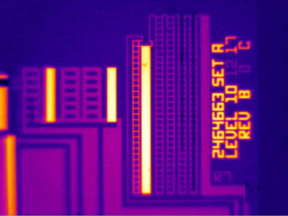
A closer view of pattern detail in the precise resistance chip, captured with a TiX560 and a 25 micron macro lens.
We scanned a circuit board and found a hot spot using a thermal imager and a standard lens. Using the Fluke 25 micron macro lens, we were able to see that the hot spot is actually two separate circuits in a single integrated circuit, both of which are working normally. If one of the circuits had failed you would be able to see that clearly on the macro image. In that case only one rectangle would be hot; the other would be dark. The image captured with the standard lens does not show enough detail to indicate two circuits. Therefore, if one was hotter than the other or cold (indicating a failure) you wouldn’t be able to see that difference and would continue to investigate other areas of the board.
Diagnosing and resolving a manufacturing problem is critical to maximizing high product yield, as we discovered in one of our own Fluke manufacturing operations. We were suddenly experiencing a much higher than average number of failures in testing our ceramic-based pyroelectric detectors. A 50 % drop in yield pointed to a manufacturing issue. From a simple power test, we found that the detector was drawing too much current, which indicated a short circuit. The problem was how to locate that short circuit.
We decided to run an infrared scan on the powered-up detector, using a high performance infrared camera. When we took an image with a standard lens attached, no anomaly appeared. However, when we attached the 25 micron macro lens, the resulting image showed a noticeable hot spot on the otherwise uniform surface.
Once we knew where the problem was, we removed the ceramic material from the detector and scanned the silicon readout chip again with the macro lens. This scan showed a clearly defined hot spot measuring about 100 microns in diameter.
Having located the region of interest, we examined the problem area on the silicon chip, with a scanning electron microscope (SEM). This examination revealed indentations in the silicon material that created a crack and caused a short circuit between the positive and negative power supply tracks. Retracing our steps in the manufacturing process we discovered that at one point in the process, the screening plate was making contact with the silicon chip, thus creating the indentation.
We adjusted the screen plate to prevent that contact, and the problem was resolved. Production yield recovered to previous levels. If we had not been able to narrow down the problem area with the macro infrared lens, it would have taken a lot longer to find the problem. We would have had to run the SEM all over the chip to find the problem, which could have taken hours rather than the minutes with a 25 micron macro lens.
The value of a macro view throughout the product cycle
Because a 25 micron macro infrared lens can focus so precisely on such small targets, it is of tremendous value for analyzing:
- Material integrity/quality
A 25 micron macro infrared lens shows thermal patterns that can indicate disjoints, lattice mismatches or other non-uniform conditions. Consistent thermal anomalies on multiple samples can point to manufacturing defects. - Material performance parameters
All materials and components have operational specifications such as temperature range and humidity. Thermal patterns can indicate whether a component or material is behaving as expected under those specified conditions. The ability to find heat differences between details as small 25 microns can help you find potential failure in near microscopic-sized components. - Material lifecycle and reliability
Capturing thermal patterns of materials over an extended test period with a macro lens can help R&D engineers determine the expected life of a component and identify areas of concern that could potentially lead to early failure.