Typical specifications for dry-well thermometer calibrators may not provide all the uncertainty information the users need to know. This paper defines other important criteria for making accurate thermometer calibrations using dry-well or “dry-block” calibrators including stability, radial uniformity, axial uniformity, hysteresis, immersion depth, differences in block loading, use of external references, etc. Examples are provided along with information on how measurements can be made and used.
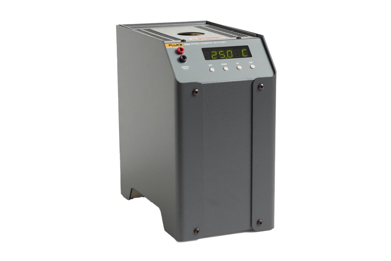
A dry-well is a useful thermometer calibration tool found in many industries from pharmaceuticals to electronics, energy, food preparation and more. Its function is to help calibrate temperature sensors against a traceable temperature standard to enhance productivity and meet regulatory requirements for both field and laboratory applications. Dry-wells are often supplied with useful features and accessories that enhance their productivity in either field or laboratory applications.
Modes of Dry-Well Calibrator Use
A dry-well commonly performs two functions. It can be used as an isothermal temperature source and as a traceable temperature reference. As an isothermal temperature source, the objective is to provide a uniform constant-temperature environment for transferring temperature data from a traceable temperature reference standard to UUTs. As a temperature standard, the calibrator itself has been calibrated.
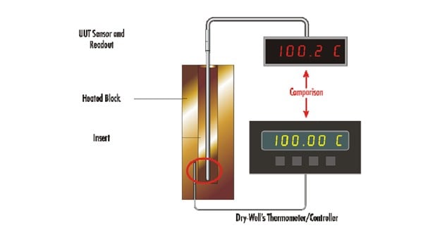
This paper refers to these two modes of using a dry-well calibrator. The direct mode utilizes the dry-well as a temperature reference standard (see Figure 1). This mode reduces the amount of equipment required, which helps reduce cost and is distinctly less cumbersome in the field.
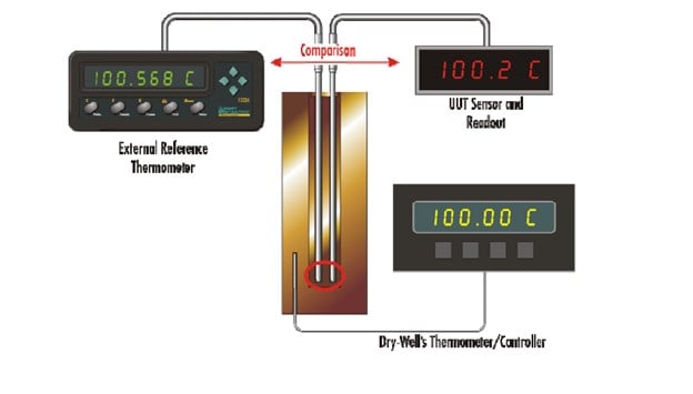
The indirect mode utilizes the dry-well as an isothermal temperature source only relying on an external thermometer (and readout) as the reference standard. (See Figure 2). It should be clarified that some drywells provide a built-in temperature readout that is separate from the dry-well’s control circuitry and sensor. This reference utilizes a separate probe that is inserted into the sleeve of the dry-well just as are the UUTs. This sensor and its associated measurement electronics may be calibrated and provide the same function as a completely external system.
Dry-well calibrator properties and their measurement
A dry-well consists of a temperature-controlled mass, usually a metal block, that provides an isothermal environment for making comparison measurements. A solid mass is much more subject to temperature gradients than is a stirred fluid bath because of reduced heat transfer throughout the solid mass. As such, those gradients are more susceptible to shifting if there are changes in the heat loss pattern through the block. Drilled holes or wells are provided in the block of the dry-well to accept thermometers. (Sleeves or inserts with different size wells are generally available to provide a proper fit for different size thermometers.) Necessarily, there is clearance between thermometer and the well to provide for easy insertion and removal (between the sleeve and block as well). This air space creates thermal resistance which again impedes heat transfer between them. Bearing these issues in mind, we shall discuss some of the properties that impact accuracy using a dry-well. These properties include temperature stability, temperature uniformity, thermal loading, temperature hysteresis, and immersion depth.
Measurement examples in this document utilize one or two input thermometer readouts. They are capable of digitally recording data rapidly enough to provide good analysis. The data collected has been imported into an Excel® spreadsheet where mathematical operations and graphing have been performed.
Temperature stability
Temperature stability is one of the most basic and commonly measured limitations to performance of a dry-well. Temperature stability is measured with a thermometer and readout with adequate sensitivity and resolution to measure the control fluctuations in the block. A thermometer response time similar to typical UUTs is also helpful. A typical time period for stability measurements of a dry-well is about 30 minutes at any specific temperature. Other time periods may be applied depending on how the calibrator is to be used. Temperature stability may vary at different temperatures. The instrument should be characterized over its range, and typically three sets of stability measurements are adequate. Dry-wells that are heated only (that is they utilize no cooling systems to achieve below-ambient temperatures) are measured at their maximum and minimum temperatures and at the midpoint of their ranges. Stability measurements for cold dry-wells are made at their maximum and minimum temperatures as well as near room temperature. Specific temperatures of interest by the user may also be incorporated.
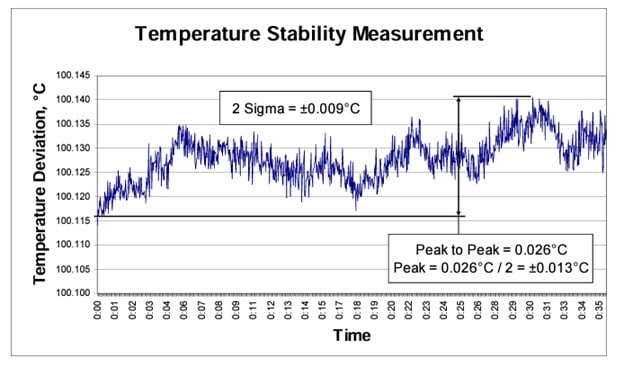
Stability is the measure of the temperature deviations over the measurement period, after temperature control has stabilized. The stability data can be viewed in two ways (see Figure 3). What may be called “peak” stability is often evaluated as plus or minus (±) one-half the difference between of the maximum and minimum values of the data set:
Peak Stability = ±(Tmax – Tmin) / 2
What may be called “2-sigma” stability is calculated as twice the standard deviation of the data set:
2-Sigma Stability = ±(2 X standard deviation)
The 2-sigma method is considered to characterize the stability more correctly, since typical temperature fluctuations tend to follow a normal probability distribution. Its result is also much less dependent on the period over which the temperature is observed.
Stability is a concern because of the time difference between measurements of the reference temperature and the UUT value. Uncertainty caused by this can be reduced by obtaining the best stability possible. Reducing the time between reference and UUT measurements can also help.
Temperature Uniformity
The temperature in the block should be axially and radially uniform or homogeneous to present the same temperature to sensors placed at different locations within the block.
All dry-wells have some level of thermal non-uniformity or inhomogeneity. Different thermometers and different thermometer types inserted into different wells for comparison experience somewhat different temperatures. Temperature differences along the length of a well are called axial gradients. Temperature differences between wells are referred to as radial gradients. These gradients can be measured, and gradient profiles determined. Uncertainties based on these profiles can be estimated and incorporated into a total uncertainty analysis.
Axial uniformity
The top and bottom of a dry-well lose heat at different rates than at the center. This tends to create a temperature gradient axially along the well. The design of the dry-well compensates for this gradient by distributing heat to varying degrees along the length of the block. These techniques are never perfect. There is always some axial gradient along a well. Any given thermometer is likely to have its sensitive area at a different depth or have a different sensitive length than the thermometer it is being compared to. For example, PRT sensors may be of different lengths and may be located at slightly different positions within their sheaths, thereby effectively sensing temperatures at different axial locations within the block. Comparing different types of sensors (such as short sensitive length thermocouples or thermistors with long sensor Standard Platinum Reference Thermometers, or SPRTs) can create a significant axial location difference making these comparisons particularly susceptible to axial gradients.
A measurement of axial gradients may be made to evaluate its effect on total uncertainty. A temperature readout with two thermometers is ideal. One of the thermometers should be a typical reference standard such as a secondary reference standard, or a PRT. The gradient thermometer, however, requires special properties. A very short temperature-sensitive portion is needed--5mm long or less is recommended. The diameter should be small as well--less than 6 mm. The design of the gradient thermometer should also be tested to demonstrate relatively low stem conduction. The sensor for the design may be PRT, thermistor, or noble metal thermocouple with an adequate temperature range to cover the desired dry-well range. Base-metal thermocouples are not suitable for these measurements because of their poor homogeneity. It is recommended that PRTs be used rather than noble metal thermocouples when practical. The stability of the thermometer is not critical if it is sufficiently stable over the duration of the test to make an accurate temperature difference measurement [1].
The measurement may be carried out at any temperature, but the deviations will usually increase as the dry-well’s temperature moves away from ambient. It is helpful in the evaluation of a dry-well to make measurements over its entire range, typically at low, medium, and high temperatures.
Measurements are made starting at the greatest depth of the well (0 mm) and withdrawing the gradient thermometer in 20 mm increments minimum. Each measurement must be given time to reestablish temperature equilibrium and stability within the well. The range of depth covered should represent the range anticipated to be covered by the sensitive lengths of the thermometers to be calibrated in the dry-well. Some SPRTs and secondary reference thermometers may have sensitive lengths of 40 to 60 mm. A typical set of measurements may include 0 mm (the bottom of the well), 20 mm, 40 mm, and 60 mm and then back to 0 mm to verify the well has not drifted. The reference thermometer remains at the bottom of one well while the gradient thermometer is moved up and down in another. The differences between the two readings will provide the desired gradient data without fluctuations due to instabilities from the dry-well’s control sensor and control electronics. (See Figure 4.)
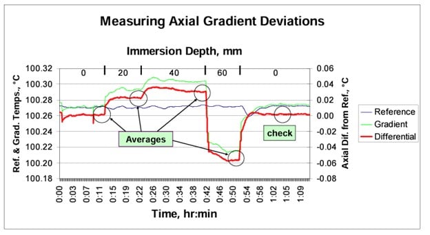
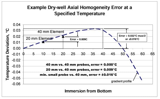
The gradient profile can be plotted as shown in Figure 5. A smooth gradient profile is an indication of accurate temperature and depth measurements.
The limits of uncertainty due to axial gradients can be estimated by calculating the maximum spread of the temperatures measured over the maximum length of the sensors to be measured in the dry-well. The example in Figure 4 shows a 0.032°C maximum error divided by 2 to provide a peak value of ±0.016°C. This is the range of error from the smallest sensor (5 mm for gradient test probe) to the largest selected of 40 mm, fully immersed in the well.
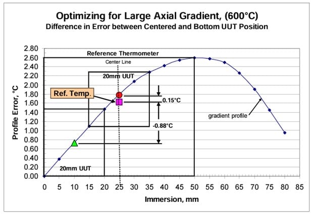
Some improvement on the uncertainty can be made if the gradient profile and the sensor lengths are accurately known. The example in Figure 5 further shows the error between the 40mm reference thermometer and a 20 mm UUT. Temperature values for each were integrated from the gradient profile curve and the error reduced. Note that using elements in probes of essentially the same design and length may eliminate the effects of axial homogeneity error altogether.
The axial homogeneity error can be one of the most significant uncertainties in the error budget. Yet a technique exists for reducing this error if the structure of the thermometers is known. Figure 6 illustrates a dry-well with a large temperature range in its gradient profile. Given the position and length of the reference sensor, its observed temperature can be estimated as before. A simple integration method of segmenting the curve by immersion depth and averaging the deviation or error values was used. The 20 mm UUT sensor length at the same immersion depth was evaluated as well and a relative error was established. If the shorter sensor is moved so that the centers of the two sensors align, the error will be much smaller, as shown in the figure [2].
Radial uniformity
Radial uniformity refers to temperature differences between wells of the block or sleeve. This nonuniformity is strongly influenced by the difference between the block and ambient temperature. A larger temperature difference from ambient will result in a larger potential temperature calibration error. Therefore, radial inhomogeneity should be measured at extremes (relative to ambient temperature) in an instrument’s temperature range.
Measuring radial homogeneity requires stable thermometers and readouts. Secondary level standards or SPRTs work best. The test must be performed within wells of equal diameters matching the thermometers to be used. Most simply done, the measurement can be made by moving a single thermometer from well to well. The dry-well must be allowed to re-stabilize each time prior to each recorded measurement.
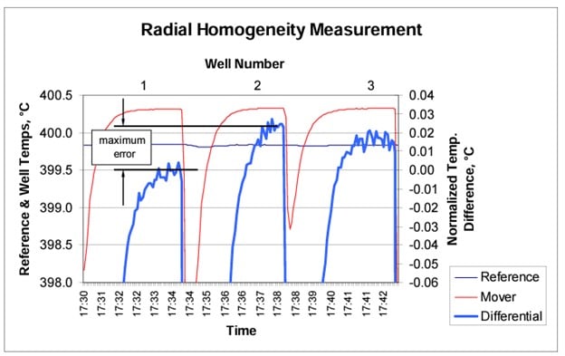
The most accurate approach is to use two thermometers with close calibrations. Use one thermometer as a reference, leaving it in the same well for the duration of the test. The second thermometer is moved from well to well, allowing the calibrator time to sufficiently stabilize at each location. Most of the control instability and drift is removed by this method, thereby isolating the temperature differences between wells. Dry-wells with a large number of wells should have at least three wells measured in as uniformly distributed a pattern as possible. Note the differences between the well temperatures. The maximum deviation between wells measured is the potential error value. The maximum error divided by 2 establishes the peak (±) error. To measure all the wells, they must be of all the same size. A minimum of two wells must be measured. (See Figure 7).
For calibrators having fewer than four wells, it may be necessary to determine differences by cyclic exchange. The difference between two wells with two thermometers may be determined with the following formula:
Temperature Difference = |((P1W1 – P1W2) + (P2W1 - P2W2)) / 2|
Note: P1 = probe 1, W1 = well 1 and so on. P1W1 is read as the value of probe 1 in well 1.
Block Loading Errors
Block loading errors occur because temperature gradients shift as heat loss or gain changes by increasing or decreasing the number and/or size of thermometers in the block. The problem is particularly noticeable when using the direct calibration mode rather than the indirect mode. In the direct mode the drywell’s control sensor was calibrated against a single reference thermometer located in the block. That calibration is transferred to UUTs in subsequent calibrations. If the sleeve is loaded with additional thermometers, the added heat loss will change the temperature distribution in the block, affecting the temperature of the thermometers while the dry-well display temperature remains the same. That change is the loading error. This error can be largely eliminated by using a reference thermometer in the sleeve, aligned with the UUTs as explained previously, thus canceling much of the additional uniformity error caused by loading.
The block loading error can be measured by inserting a monitoring thermometer into a well of the sleeve and recording its temperature over a period of time. After the temperature has been established, add more thermometers one at a time and observe the changes in the dry-well’s display and monitor thermometer’s temperatures. The added thermometers need not be actively measured but are needed simply to mimic the thermal load of adding more thermometers. The dry-well’s display will always work its way back to the set-point temperature after a disturbance. However, the reference thermometer’s readout will indicate a change in temperature with each added load. Reverse the process by removing the inactive thermometers to assure that the original temperature is repeated. See Figure 8 for an example of test data. Typical block loading errors can be determined in this way and added into the uncertainty budget appropriately.
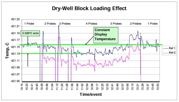
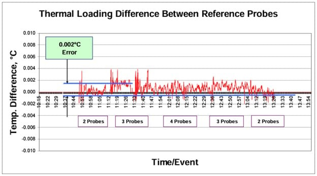
Adding a second reference to the block (as shown in Figure 8 as “Ref 2”) can provide data for testing the loading effect on the indirect mode of measurement. A differential value is calculated from the two curves, as is shown in Figure 9. The changes are small for this type of calibration compared to those of the direct calibration mode.
Temperature Hysteresis
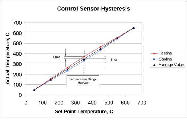
Hysteresis in the dry-well calibrator is the result of varying strain in the industrial platinum resistance thermometer (IPRT) used to control the temperature of the dry-well. The pattern is fairly reproducible, yet it varies with the temperature range of the current temperature cycle. As the dry-well cycles between the minimum and maximum set-point temperatures, the actual measured temperature will vary most at the midpoint temperature of the range. The direction of error depends on whether the unit is going in the heating or cooling direction. Typical IPRT resistances are low when heating and high when cooling. When the IPRT is installed in a dry-well as a temperature control sensor, the sense is reversed by the controller and the set-point temperature will be higher when heating and lower when cooling. The difference between the minimum and maximum temperature at the midpoint of the range may vary from zero to some tenths of a degree C. The hysteresis error at the midpoint of the range varies with IPRT designs and even between different elements of the same design. The dry-well’s quantified hysteresis is taken to be the difference between the maximum and minimum temperatures as measured by a reference thermometer at the midpoint of the excursion range of the instrument. (See Figure 10.)
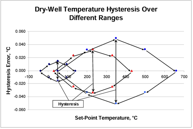
Measuring the hysteresis is carried out by recording multiple thermal cycles between the maximum and minimum temperatures of the dry-well’s range using a good hysteresis-free reference thermometer. Note that smaller excursion ranges will result in smaller hysteresis errors. There may be an excursion range that yields practically no hysteresis at all [3] [4]. (See Figure 11).
Immersion error
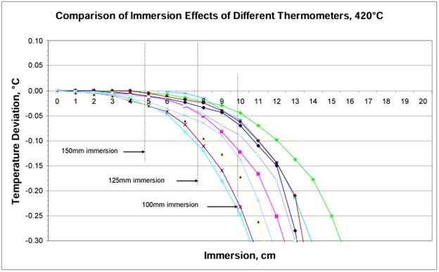
Immersion error comes about because of stem conduction of a thermometer. The thermometer stem is the portion of the thermometer probe between the sensor and the lead wires. Stem conduction is caused by heat flowing from the senor along the stem of the thermometer to the ambient environment. IF the sensor can be immersed into the isothermal block far enough so that a portion of the stem above the sensor reaches the same temperature as the block, no heat would flow through the sensor. When that occurs for reference and UUTs, they will equilibrate to the same temperature.
While stem conduction is a property of the thermometer and not of the calibrator, immersion depth is. Ideally, all the thermometers will be immersed far enough into the block so that stem conduction is negligible. The key then is having sufficient immersion depth for the reference thermometer and UUTs to overcome the problem.
In order to determine whether stem conduction error is significant, a uniform temperature source is required. If a particular dry-well has been measured for axial gradients and found adequate, it may be used for the stem conduction test. If the dry-well has significant axial gradients it will be difficult to separate the axial gradient from the stem conduction effects. Significant temperature gradients in the source invalidates the result.
A simple stem conduction test is similar to the axial gradient test. A reference thermometer and the test thermometer are monitored with an adequate readout. The two thermometers are placed in the bottom of appropriately sized wells. The dry-well is set to the desired temperature and the thermometers are allowed to equilibrate. The difference between the temperature values is noted and the thermometer under test is raised 10 mm and permitted to equilibrate. The difference between the two sensors is again noted and the two differences are evaluated. A temperature shift toward ambient is typical of a stem conduction effect. No significant change would suggest there is little stem conduction error.
Figure 12 illustrates immersion curves of several different thermometer designs in a gradient free dry-well. If the reference and test thermometers have identical construction so that thermal loss/gain properties are the same, the stem conduction error will be minimized.
Uncertainty budget
To establish the uncertainty of a calibration process that uses a dry-well, all of the limits of error must first be quantified. Each temperature measurement made in a dry-well will likely be found in a quantifiable range or band of uncertainty.
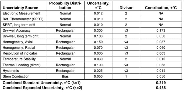
An uncertainty budget is the statistical aggregation of the individual sources of uncertainties of the instruments utilized in a calibration according to their application and use. Two examples are provided below. The first example applies the direct mode of calibration--or in other words uses the displayed temperature of dry-well itself and as the reference temperature. The second example applies the indirect mode and utilizes an external calibration reference thermometer and readout.
The uncertainty list below has been established for general dry-well use. Individual line items may or may not apply to all situations depending on the specific mode of the dry-well used. An explanation of each item’s applicability to the mode utilized in the examples is explained. A probability distribution has been selected for each category. A divisor is also applied according to the distribution type and k factor. The uncertainties have been listed and combined by the root-sum-square method at the bottom of the charts below assuming uncertainties are uncorrelated. The examples are taken with typical uncertainties found at the temperature of 200°C over a 40 mm measurement zone. Some uncertainties have been combined for simplicity in these examples. A probability distribution has been selected according to assumptions concerning the data and for simplicity. The user’s own evaluation of distribution should be applied.
Uncertainty application glossary
Electronic Measurement of Reference: The uncertainties of the electronics used to measure and display temperature of the reference thermometer have been determined from the manufacturer’s specifications and method of use to be ±0.012°C (k=2) which includes self-heating of the thermometer. This applies to indirect but not to direct modes.
Reference Thermometer: The calibration of the resistance thermometer (SPRT) used as a calibration reference has an expanded uncertainty at 200°C of ±0.010°C (k=2). This applies to indirect but not to direct modes.
Reference Thermometer Long Term Drift: The drift specification for the SPRT in our example has been determined to be ±0.010°C (k=2). This applies to indirect but not to direct modes.
Dry-well Accuracy: The manufacturer has specified the total accuracy to be ±0.300°C. This applies to direct but not to indirect modes.
Dry-well Calibrator Long Term Drift: Calibration records show that long term drift of the instrument is within ±0.100°C. This applies to direct but not to indirect modes.
Homogeneity, Axial: The range of error in the measurement zone is 0.300°C, providing a peak value of ±0.150°C. For the indirect mode an added axial gradient uncertainty of ±0.070 was added for the SPRT.
Homogeneity, Radial: The maximum difference between wells at this calibration set point was estimated to be 0.140°C for a peak value of ±0.070°C. For the indirect mode an added radial gradient uncertainty of ±0.070 was added for the SPRT, its length and location having been evaluated.
Resolution, Indicator: The resolution of the dry-well’s temperature indicator is 0.01°C, establishing temperature resolution limits of ±0.005°C.
Temperature Stability: The temperature stability of the calibrator at this set temperature for over a 30-minute period was estimated to be ±0.030°C using a 2-sigma method.
Thermal Loading: The maximum effect thermal loading for the dry-well using the direct calibration method was 0.200°C or ±0.100°C. For the indirect mode, it was found to be ±0.002°C.
Hysteresis: The maximum temperature error determined from heating and cooling cycles is estimated to be within 0.050°C or ±0.025°C.
Stem Conduction or Immersion Error: The stem conduction of the thermometers used at a particular immersion depth has been estimated to be 0.050°C.
Calculation examples
The following tables illustrate the calculations of the combined standard uncertainties and combined expanded uncertainties for the direct and indirect calibration modes.
Direct Measurement Example
Indirect Measurement Example
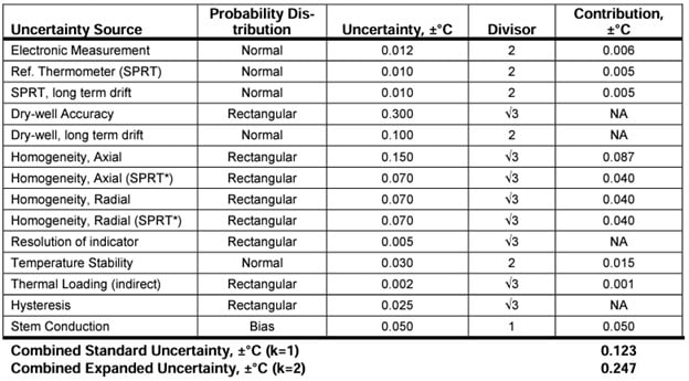
Note: *An axial and radial uncertainty has been added in the indirect mode example for the SPRT. This uncertainty is accounted for in the direct mode in the dry-well accuracy uncertainty.
There are several properties inherent in all dry-well calibrators that to some degree contribute to the inaccuracy of the thermometer calibration process. An estimate of the inaccuracy can be measured in terms of its uncertainty with the techniques provided in this paper. Different modes of use of the dry-well also contribute to levels of uncertainty as well. These uncertainties can then be combined to provide a statistically robust total uncertainty for the calibration of thermometers in a given dry-well calibrator.