Part 3 of this five-part series describes how to trigger an oscilloscope so it displays a signal the way you want, and how the oscilloscope's inputs are isolated.
You can view the preceding installment of this series, Signal Input and Processing. You can also view the complete webinar with audio and animations at the Fluke Training Center.
Triggering
You can think of oscilloscope triggering as capturing a series of photo "snapshots" that are then printed on clear transparencies.
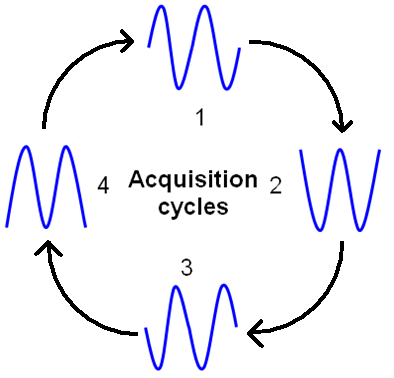

Acquiring a signal
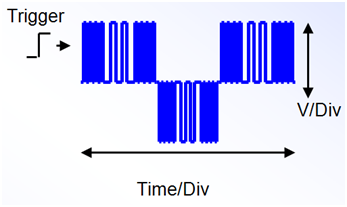
As each transparency is acquired and placed one on top of the preceding one, a picture of the signal is built. However, if the pictures aren't placed correctly, the image doesn't look right, as shown below.
An untriggered signal can appear distorted
By choosing a point on the input signal to use as a trigger ("T" volts in the image below), the "snapshot" images can be displayed at the right time and in the right location, giving a stable and useful waveform display.
An oscilloscope uses several techniques to "trigger" or synchronize the display.

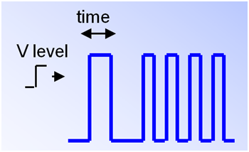
- If you select edge triggering, the trigger fires and displays the waveform when the detected voltage rises or falls through a trigger voltage that you set.
- With pulse width triggering, the trigger fires and displays the waveform only when both the voltage level and a pre-determined time interval condition are met. Using pulse width triggering, you can synchronize on very specific pulses in a stream of pulses.
- Connect & View is a proprietary algorithm for the Fluke ScopeMeter that automatically and continuously analyses an unknown signal and then adjusts the scope's vertical, horizontal, and trigger settings to give a stable display. It virtually eliminates the need for continual scope adjustment at every test point. Because Connect & View can capture an unknown waveform without the user having to know anything about the waveform amplitude, time, or triggering dynamics, it's a good starting point for setting up the oscilloscope display.
Trace Display Update
The trace display update can be controlled, the typical choices are:
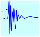
- Continuous or "free run," updates the display regardless of the trigger condition. A live trace can be seen even with no input signal. This is the default update mode on Fluke ScopeMeters.
- On trigger refreshes the display only when a valid trigger condition occurs. Otherwise, the trace freezes on the display, waiting for a valid trigger to occur before updating or refreshing the display. This mode typically provides the fastest display refresh or update rate.
- Single Shot triggering refreshes the display one time only. It is a great tool for capturing "one-off," never-to-be-repeated events. To use single shot, set up the vertical and the horizontal sensitivity, and then "arm" the scope with the single shot trigger. When the trigger condition is met, the scope updates the display one time and then freezes, allowing you to analyze the event for as long as needed. You must manually re-arm the scope for it to acquire another waveform and update the display.
Isolation
Fluke ScopeMeter test tools have insulated BNC input connectors and isolated power adapters that provide a safe means to float the oscilloscope input above earth ground reference.
Both input Channel A reference and Channel B reference are isolated from earth ground. On some Fluke ScopeMeter models (such as the 196C, 199C, 215C, and the 225C) the input A reference and input B reference are also electrically isolated from each other, making it possible to perform differential measurements without the need for an external differential amplifier or specialized accessory.
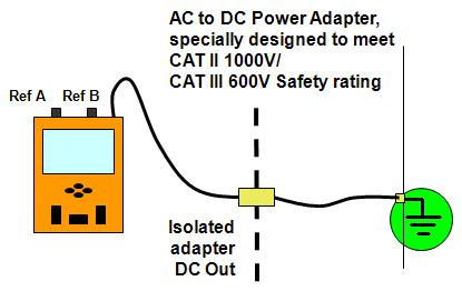
A typical bench oscilloscope input reference and chassis are electrically tied to earth ground to protect against electrical shock. To be safe, all exposed metal conductors (chassis and BNC connectors) are tied to earth ground. Connecting the bench scope reference input directly to anything other than earth ground can present an unsafe condition to the user. Specialized scope differential input probes are required to measure a voltage floating relative to earth ground reference.
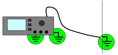
A bench scope's input channel references cannot be connected to two different voltages. Furthermore, the reference points must be connected to earth ground at the circuit under test, otherwise you could inadvertently create a short circuit through the mains earth ground connection.
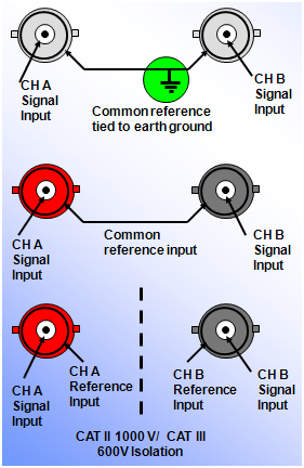
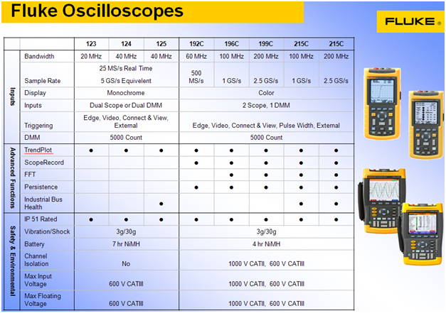
The ScopeMeter 120 series input references are tied together, while the 19XC/2X5C series input reference is electrically isolated providing the optimum solution for troubleshooting differential signals. Again, with the Fluke ScopeMeter the reference point can be connected to a voltage other than earth ground, safely floating the oscilloscope.
Of course, it is very important that you read and understand the user instructions, specifications, and safety warnings for any oscilloscope before you use it.
Fluke Oscilloscopes
The concepts and techniques presented here can be explored with the entire range of Fluke portable oscilloscopes. Available in bandwidths from 20 MHz to 200 MHz, Fluke ScopeMeters have the performance and features to tackle a wide variety of measurements, from routine troubleshooting to demanding tasks like finding random events. Fluke oscilloscopes are specifically designed to operate in harsh environments - out of the lab away from a bench.
- ABCs of Portable Oscilloscopes: Part 1, Multimeters and Oscilloscopes
- ABCs of Portable Oscilloscopes: Part 2, Signal Input and Processing
- ABCs of Portable Oscilloscopes: Part 4, Capturing and Analyzing Waveforms
- ABCs of Portable Oscilloscopes: Part 5, Capturing Intermittent and Random Events with a Portable Oscilloscope